
SPI Test 1 (Serial Flash Memory Test)
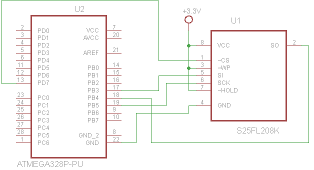
Connection Diagram
Functions
Most of functions required to interface with a serial flash memory device(S25FL208K) are implemented in <S25FL208K_hal.c> file.
A demo program <SPI_Serial_Flash_S25FL208K.c> was developed to test the functions implemented in <S25FL208K_hal.c> file.
How to test
1. Connect the serial flash memory device to a arduino nano board. Refer to the above connection diagram.
2. Connect the arduino nano USB connector to a laptop or desktop USB connector.
3. Run a terminal program on PC and set the communication parameters as following:
9600 bps, 8 data bit, no parity, one stop bit
4. Main menu will be dispalyed on the terminal screen as below. User can select one of ten test functions and see the test result.
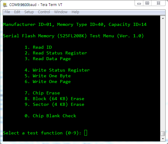
User can select one of ten test functions and see the test result.
Demo Program to Test the Library Functions
SPI_Serial_Flash_S25FL208K.c
/************************************************************
SPI interface with Spansion Serial Flash Memory S25FL208K

Date    : 2015-03-06
Author  : J.M. Cho
Chip type               : ATmega328P
AVR Core Clock frequency: 16.000000 MHz

PD7        -->  CS#(1)
PB5(SCK)   -->  SCK(6)
PB4(MISO)  <--  SO(2)
PB3(MOSI)  -->  SI(5)
-----------------------------------------------------
<USART Spec>
    9600, 8, N, 1
-----------------------------------------------------
<Compiler Settings>
To support unsigned long int (uint32_t)
CodeVision setting should be changed as following:

    (Top Menu)
        Project ->  Configure -> C Compiler tab

    (In the C Compiler tab)
        (s)printf Features: long, width, precision
        (s)scanf Features: long, width
*****************************************************/

#include <mega328p.h>
#include <stdio.h>
#include <S25FL208K_hal.h>
#include <SPI_Serial_Flash_S25FL208K.h>


const char msg_byte_data_req[]          = "Enter 1-byte value in HEX (0x00-0xFF): ";
const char msg_3byte_addr_req[]         = "Enter 3-byte address in HEX (0x000000-0xFFFFFF): ";
const char msg_3byte_block_addr_req[]   = "Enter 3-byte BLOCK start address in HEX (0x000000-0xFFFFFF): ";
const char msg_3byte_sector_addr_req[]  = "Enter 3-byte SECTOR start address in HEX (0x000000-0xFFFFFF): ";

void main(void)
{
    uint8_t buf[256] = {0, };   // initialize 256 byte of buf with zero
    int sel, ret_val;
    uint32_t addr;
    uint8_t temp;

    init_system();

    smem_read_JEDEC_ID(buf);
    // Screen shows you 01, 40, 14
    printf("\n\rManufacturer ID=%02X, Memory Type ID=%02X, Capacity ID=%02X\n\r", buf[0], buf[1], buf[2]);

    while (1)
    {
        sel = display_menu();
        switch (sel)
        {
            // Read ID
            case 1:
                smem_read_JEDEC_ID(buf);
                printf("\n\rManufacturer ID=0x%02X, Memory Type ID=0x%02X, Capacity ID=0x%02X\n\r", buf[0], buf[1], buf[2]);
                break;

            // Read Status Register
            case 2:
                temp = smem_read_status_register();
                printf("\n\rStatus Register Value=0x%02X\n\r", temp);
                break;

            // Read Data Page
            case 3:
                addr = display_menu_mem_read();     // get memory address to read
                addr &= 0xFFFF00;                   // convert to page start address
                smem_read_data_page(buf, addr);     // read one page
                display_buf(buf, addr);             // display it
                break;

            // Write Status Register
            case 4:
                temp = display_menu_stat_reg();     // get 8-bit value to be written
                smem_write_status_register(temp);   // write it to status reg
                break;

            // Write One Byte
            case 5:
                addr = display_menu_one_byte(buf);      // get 8-bit data and 24-bit address
                smem_write_data(buf, addr, 1);          // write one byte to flash
                break;

            // Write One Page
            case 6:
                addr = display_menu_one_page(buf);      // get 8-bit data and 24-bit address
                smem_write_data(buf, addr, 256);        // write one page to flash
                break;

            // Chip Erase
            case 7:
                printf("\n\rWait...it takes few seconds. ");
                smem_erase_chip();
                printf("\n\rChip erased.\n\r");
                break;

            // Block Erase
            case 8:
                addr = display_menu_block_erase();
                smem_erase_block(addr);
                printf("\n\rBlock erased.\n\r");
                break;

            // Sector Erase
            case 9:
                addr = display_menu_sector_erase();
                smem_erase_sector(addr);
                printf("\n\rSector erased.\n\r");
                break;

            // Chip Blank Check
            case 0:
                printf("\n\rWait...it takes few seconds. ");
                ret_val = smem_chip_blank_check();
                if (ret_val == SMEM_BLANK)
                    printf("\n\rChip is BLANK.\n\r");
                else
                    printf("\n\rChip is NOT blank.\n\r");
                break;
        }

    }
}

void init_system(void)
{
    // Crystal Oscillator division factor: 1
    #pragma optsize-
    CLKPR=0x80;
    CLKPR=0x00;
    #ifdef _OPTIMIZE_SIZE_
    #pragma optsize+
    #endif

    // Input/Output Ports initialization
    // Port B initialization
    // Func7=In Func6=In Func5=Out Func4=In Func3=Out Func2=In Func1=In Func0=In
    // State7=T State6=T State5=0 State4=T State3=0 State2=T State1=T State0=T
    // ***********************************************************************
    // Important Note on SS(PB2)
    // -------------------------
    // SS(PB2) is not used as a Slave Select signal in this example - instead,
    // PD7 is used as a Chip Select signal for the Serial Flash Memory chip.
    // However, PB2 should be set to ONE(1) regardless of its data direction.
    // If PB2 is set to ZERO(0),
    //      SPIF flag is never set to ONE after transmission of the second byte.
    // Refer to 19.3.2 (page 165) of the datasheet.
    //
    // Conclusion:
    //  Use PB2 as an SS control signal for your first SPI device.
    // ***********************************************************************
    PORTB = 0x04;     // MUST write 1 to PB2 (SS)
    DDRB  = 0x2C;

    // Port D initialization
    // Func7=Out Func6=In Func5=In Func4=In Func3=In Func2=In Func1=In Func0=In
    // State7=1 State6=T State5=T State4=T State3=T State2=T State1=T State0=T
    // PD7 is used as a Chip Select signal for the Serial Flash Memory chip.
    PORTD = 0x80;
    DDRD  = 0x80;

    // USART initialization
    // Communication Parameters: 8 Data, 1 Stop, No Parity
    // USART Receiver: On
    // USART Transmitter: On
    // USART0 Mode: Asynchronous
    // USART Baud Rate: 9600
    UCSR0A=0x00;
    UCSR0B=0x18;
    UCSR0C=0x06;
    UBRR0H=0x00;
    UBRR0L=0x67;

    // SPI initialization
    // SPI Type: Master
    // SPI Clock Rate: 8 MHz (SYSCLK / 2)
    // SPI Clock Phase: Cycle Start
    // SPI Clock Polarity: Low
    // SPI Data Order: MSB First
    SPCR=0x50;      // 0101 0000
    SPSR=0x01;
}

uint32_t display_menu_sector_erase(void)
{
    uint32_t addr;

    // get address to be written
    addr = get_24bit_addr(msg_3byte_sector_addr_req);

    return addr;
}

uint32_t display_menu_block_erase(void)
{
    uint32_t addr;

    // get address to be written
    addr = get_24bit_addr(msg_3byte_block_addr_req);

    return addr;
}

// Get 8-bit data to be written in the page
// On Return:
//  t[]: filled with user input byte
//  return value: start address of a page
uint32_t display_menu_one_page(uint8_t t[])
{
    uint32_t addr;
    int i;
    uint8_t data;

    // get data to be written
    data = get_byte(msg_byte_data_req);

    // fill in the buffer with user data
    for (i=0; i<256; i++)
    {
        t[i] = data;
    }

    // get address to be written
    addr = get_24bit_addr(msg_3byte_addr_req);

    return addr;
}

uint32_t display_menu_one_byte(uint8_t t[])
{
    uint32_t addr;

    // get data to be written
    t[0] = get_byte(msg_byte_data_req);

    // get address to be written
    addr = get_24bit_addr(msg_3byte_addr_req);

    return addr;
}

// get three bytes of address from user
uint32_t get_24bit_addr(char msg[])
{
    long int addr_val;
    uint32_t addr;
    char res;

    do
    {
        printf("\n\r%s", msg);
        res = scanf("%lx", &addr_val);
    } while (res != 1 || addr_val > 0xFFFFFF || addr_val < 0);

    addr = (uint32_t)(addr_val & 0xFFFFFF);

    return addr;
}

// get one byte of data from user
uint8_t get_byte(char msg[])
{
    int data;
    char res;
    uint8_t ret_val;

    do
    {
        printf("\n\r%s", msg);
        res = scanf("%x", &data);
    } while (res != 1 || data > 0xff || data < 0);

    ret_val = (uint8_t)(data & 0xFF);

    return ret_val;
}

// get one byte of data to be written in status register
uint8_t display_menu_stat_reg(void)
{
    uint8_t ans;

    ans = get_byte(msg_byte_data_req);

    return ans;
}

//int display_menu_mem_read(void)
uint32_t display_menu_mem_read(void)
{
    uint32_t addr;

    // get address to be written
    addr = get_24bit_addr(msg_3byte_addr_req);

    return addr;
}

// dispaly main menu and get user selection
int display_menu(void)
{
    int ans = 0;

    do
    {
        printf("\n\rSerial Flash Memory (S25FL208K) Test Menu (Ver. %d.%d)\n\r\n\r", VERSION_MAJOR, VERSION_MINOR);
        printf("\t1. Read ID\n\r");
        printf("\t2. Read Status Register\n\r");
        printf("\t3. Read Data Page\n\r\n\r");

        printf("\t4. Write Status Register\n\r");
        printf("\t5. Write One Byte\n\r");
        printf("\t6. Write One Page\n\r\n\r");

        printf("\t7. Chip Erase\n\r");
        printf("\t8. Block (64 KB) Erase\n\r");
        printf("\t9. Sector (4 KB) Erase\n\r\n\r");

        printf("\t0. Chip Blank Check\n\r\n\r");

        printf("\n\rSelect a test function (0-9): ");

        scanf("%d", &ans);
    } while (ans < 0 || ans > 9);

    return ans;
}

// Display 256 bytes stored in buf[256]
void display_buf(uint8_t buf[], uint32_t addr)
{
    int i;

    for (i=0; i<256; i++)
    {
        if (i%8 == 0)
        {
            if  (i%16 == 0)
                printf("\n\r%06lX: ", addr+i);
            else
                printf("- ");
        }
        printf("%02X ", buf[i]);
    }
    printf("\n\r");
}

// end of file
SPI_Serial_Flash_S25FL208K.h
//
// SPI_Serial_Flash_S25FL208K.h
//

int display_menu(void);
uint32_t display_menu_mem_read(void);
uint8_t display_menu_stat_reg(void);
uint32_t display_menu_one_byte(uint8_t t[]);
uint32_t display_menu_one_page(uint8_t t[]);
uint32_t display_menu_block_erase(void);
uint32_t display_menu_sector_erase(void);
int smem_chip_blank_check(void);

void display_buf(uint8_t buf[], uint32_t addr);

uint8_t get_byte(char msg[]);
uint32_t get_24bit_addr(char msg[]);

void init_system(void);

// end of file
Implemented Library Functions
S25FL208K_hal.c
/********************************************************************
 SPI interface function with Spansion Serial Flash Memory S25FL208K
Date    : 2015-03-06
Author  : J.M. Cho
Chip type               : ATmega328P
AVR Core Clock frequency: 16.000000 MHz

PD7        -->  CS#(1)
PB5(SCK)   -->  SCK(6)
PB4(MISO)  <--  SO(2)
PB3(MOSI)  -->  SI(5)

-------------------------------------------------------------------
<Compiler Settings>
To support unsigned long int (uint32_t)
CodeVision setting should be changed as following:

    (Top Menu)
        Project ->  Configure -> C Compiler tab

    (In the C Compiler tab)
        (s)printf Features: long, width, precision
        (s)scanf Features: long, width
********************************************************************/

#include <mega328p.h>
#include <S25FL208K_hal.h>    // user defined header file

// Erase a sector (4 kbytes)
void smem_erase_sector(uint32_t addr)
{
    // Enable write
    smem_write_enable();

    // Set #CS LOW
    smem_assert_cs();

    // Send a command
    SPDR = CMD_SECT_ERASE;
    while (!(SPSR & 0x80));

    // Set A23-A16 address
    SPDR = addr >> 16;
    while (!(SPSR & (1 << SPIF)));

    // Set A15-A8 address
    SPDR = addr >> 8;
    while (!(SPSR & (1 << SPIF)));

    // Set A7-A0 address
    SPDR = addr & 0xFF;
    while (!(SPSR & (1 << SPIF)));

    // Set #CS HIGH
    smem_negate_cs();

    // wait for completeness of the given command
    while (smem_read_status_register() & STAT_BUSY_BIT);
}

// Erase a block (64 kbytes)
void smem_erase_block(uint32_t addr)
{
    // Enable write
    smem_write_enable();

    // Set #CS LOW
    smem_assert_cs();

    // Send a command
    SPDR = CMD_BLK_ERASE;
    while (!(SPSR & 0x80));

    // Set A23-A16 address
    SPDR = addr >> 16;
    while (!(SPSR & (1 << SPIF)));

    // Set A15-A8 address
    SPDR = addr >> 8;
    while (!(SPSR & (1 << SPIF)));

    // Set A7-A0 address
    SPDR = addr & 0xFF;
    while (!(SPSR & (1 << SPIF)));

    // Set #CS HIGH
    smem_negate_cs();

    // wait for completeness of the given command
    while (smem_read_status_register() & STAT_BUSY_BIT);
}

// Erase whole chip
void smem_erase_chip(void)
{
    // Enable write
    smem_write_enable();

    // Set #CS LOW
    smem_assert_cs();

    // Send a command
    SPDR = CMD_CHIP_ERASE;
    while (!(SPSR & 0x80));

    // Set #CS HIGH
    smem_negate_cs();

    // wait for completeness of the given command
    while (smem_read_status_register() & STAT_BUSY_BIT);
}

// Read status register and return it
uint8_t smem_read_status_register(void)
{
    // Set #CS LOW
    smem_assert_cs();

    // Send Read Status Register command (0x05, p.16)
    SPDR = CMD_RD_STAT_REG;
    while (!(SPSR & 0x80));

    // Read in Status Register value
    SPDR = 0x00;
    while (!(SPSR & (1 << SPIF)));

    // Set #CS HIGH
    smem_negate_cs();

    return SPDR;
}

// Write Status Register
void smem_write_status_register(uint8_t stat)
{
    // Enable write
    smem_write_enable();

    // Set #CS LOW
    smem_assert_cs();

    // Send Write Status Register command (0x01, p.17)
    SPDR = CMD_WR_STAT_REG;
    while (!(SPSR & 0x80));

    // Write value to Status Register
    SPDR = stat;
    while (!(SPSR & 0x80));

    // Set #CS HIGH
    smem_negate_cs();

    // wait for completeness of flash program
    while (smem_read_status_register() & STAT_BUSY_BIT);
}

// Set Write Enable Latch bit to 1
void smem_write_enable(void)
{
    // Set #CS LOW
    smem_assert_cs();

    // Send Write Enable command (0x06, p.15)
    SPDR = CMD_WR_ENABLE;
    while (!(SPSR & 0x80));

    // Set #CS HIGH
    smem_negate_cs();
}

void smem_write_data(uint8_t buf[], uint32_t addr, int count)
{
    int i;

    // Enable write
    smem_write_enable();

    // Set #CS LOW
    smem_assert_cs();

    // Send a command
    SPDR = CMD_WR_PAGE;
    while (!(SPSR & 0x80));

    // Set A23-A16 address
    SPDR = addr >> 16;
    while (!(SPSR & (1 << SPIF)));

    // Set A15-A8 address
    SPDR = addr >> 8;
    while (!(SPSR & (1 << SPIF)));

    // Set A7-A0 address
    SPDR = addr & 0xFF;
    while (!(SPSR & (1 << SPIF)));

    for (i=0; i<count; i++)
    {
        // write data
        SPDR = buf[i];
        while (!(SPSR & (1 << SPIF)));
    }

    // Set #CS HIGH
    smem_negate_cs();

    // wait for completeness of flash program
    while (smem_read_status_register() & STAT_BUSY_BIT);
}

void smem_read_JEDEC_ID(uint8_t t[])
{
    // Set #CS LOW
    smem_assert_cs();

    // Send RDID command (0x9F, p.26 and 27)
    SPDR = CMD_RD_ID;
    while (!(SPSR & 0x80));

    // Read Manufacturer ID
    SPDR = 0x00;
    while (!(SPSR & (1 << SPIF)));
    t[0] = SPDR;

    // Read Memory Type ID
    SPDR = 0x00;
    while (!(SPSR & (1 << SPIF)));
    t[1] = SPDR;

    // Read Capacity ID
    SPDR = 0x00;
    while (!(SPSR & (1 << SPIF)));
    t[2] = SPDR;

    // Set #CS HIGH
    smem_negate_cs();
}

// Read 256 bytes of data from serial flash memory
// Refer to Section 8.5 (page 18) of datasheet
void smem_read_data_page(uint8_t t[], uint32_t addr)
{
    int i;

    // Set #CS LOW
    smem_assert_cs();

    // Send Data Read command (0x03, p.18)
    SPDR = CMD_RD_DATA;
    while (!(SPSR & 0x80));

    // Set A23-A16 address
    SPDR = addr >> 16;
    while (!(SPSR & (1 << SPIF)));

    // Set A15-A8 address
    SPDR = addr >> 8;
    while (!(SPSR & (1 << SPIF)));

    // Set A7-A0 address
    SPDR = addr & 0xFF;
    while (!(SPSR & (1 << SPIF)));

    for (i=0; i<256; i++)
    {
        // Read data
        SPDR = 0x00;
        while (!(SPSR & (1 << SPIF)));

        t[i] = SPDR;
    }

    // Set #CS HIGH
    smem_negate_cs();
}

// chip blank check
// On return:
//  1: Blank,  0:Not Blank
int smem_chip_blank_check(void)
{
    uint32_t addr;
    uint8_t data;

    // Set #CS LOW
    smem_assert_cs();

    // Send Data Read command (0x03, p.18)
    SPDR = CMD_RD_DATA;
    while (!(SPSR & 0x80));

    // Set A23-A16 address
    SPDR = 0;
    while (!(SPSR & (1 << SPIF)));

    // Set A15-A8 address
    SPDR = 0;
    while (!(SPSR & (1 << SPIF)));

    // Set A7-A0 address
    SPDR = 0;
    while (!(SPSR & (1 << SPIF)));

    for (addr=0; addr<SMEM_LAST_ADDR; addr++)
    {
        // Read data
        SPDR = 0x00;
        while (!(SPSR & (1 << SPIF)));

        data = SPDR;

        if (data != 0xff)
            return SMEM_NOT_BLANK;
    }

    // Set #CS HIGH
    smem_negate_cs();

    return SMEM_BLANK;
}

void smem_assert_cs(void)
{
    PORTD &= ~SMEM_CS;
}

void smem_negate_cs(void)
{
    PORTD |= SMEM_CS;
}

// end of file
S25FL208K_hal.h
//
// S25FL208K_hal.h
//

#include <def.h>

void smem_read_JEDEC_ID(uint8_t t[]);
void smem_write_enable(void);
uint8_t smem_read_status_register(void);
void smem_write_status_register(uint8_t stat);
void smem_read_data_page(uint8_t t[], uint32_t addr);
void smem_write_data(uint8_t buf[], uint32_t addr, int count);
void smem_erase_sector(uint32_t addr);
void smem_erase_block(uint32_t addr);
void smem_erase_chip(void);
int smem_chip_blank_check(void);

void smem_assert_cs(void);
void smem_negate_cs(void);

// end of file
def.h
//
// def.h
//

// software version
#define VERSION_MAJOR   1
#define VERSION_MINOR   0


// Serial Flash Memory used by the following function.
//  smem_chip_blank_check()
#define SMEM_LAST_ADDR  0x0FFFFF
#define SMEM_BLANK      1
#define SMEM_NOT_BLANK  0

// Chip Selection signal for Serial Flash Memory
#define SMEM_CS         0x80    // Chip Select, PD7

// Command used by Serial Flash Memory
#define CMD_RD_ID       0x9F
#define CMD_RD_DATA     0x03
#define CMD_WR_ENABLE   0x06
#define CMD_WR_PAGE     0x02
#define CMD_RD_STAT_REG 0x05
#define CMD_WR_STAT_REG 0x01
#define CMD_SECT_ERASE  0x20
#define CMD_BLK_ERASE   0xD8
#define CMD_CHIP_ERASE  0xC7

// BUSY(WIP) bit position in status register
#define STAT_BUSY_BIT   0x01

typedef unsigned char       uint8_t;
typedef unsigned int        uint16_t;
typedef unsigned long int   uint32_t;

// end of file