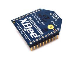
How to connect XBee S1 to Arduino Nano (AT Command mode)
Objective
To develop a wireless communication system using XBee S1 module and Arduino Nano
Test Environment
Step I: Preparation of XBee Modules
- Set the "B" part of the board (refer to the photo below) so that the board outputs 3.3V at the VCC pin of the UC00B board.
- Installation of the driver software: refer to the user's manual for this board.
- Two types of SparkFun FTDI Basic Breakout boards are available in the market, so you have to check its output voltage at the VCC pin as following.
- (Look at the yellow circle in left-side photo below) If the top side of the board is marked with 3.3V you can use the board without any modification.
- (Look at the yellow circle in middle photo below) If your board is marked with 5V change the VCC selection solder bridge at the bottom side of the board as indicated in the right-side photo below. (in green color block)
- Installation of the driver software: refer to the SparkFun home page.
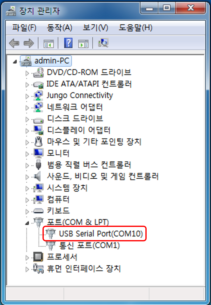
- Open the Windows's "Device Manager" and take a note of its virtual COM port number. (COM10 in the photo below)
- The XBee S1 goes to sleep mode if the SM parameter is 1 or 2 and voltage at pin 9 is VCC. By default, the voltage at pin 9 is VCC if this pin is not connected.
- The XBee S1 wakes up from sleeping mode by applying GND level voltage to pin 9 and stays in awake mode as long as voltage at pin 9 is GND level.
- The SM parameter value can be changed to 0 while voltage at pin 9 is GND level.
1. Read Xbee S1 module datasheet and analyze its operation.
A. What the transparent mode is.
B. The function of SLEEP_RQ pin (pin 9) and module status indicator pin (pin 13).
C. Power consumption during transmission, idling/receiving and power-down states.
2. The maximum allowable VCC voltage of the XBee S1 module is 3.4V and we will supply this VCC voltage from the UART-USB Signal Conversion module (FT-232 module). Since the FT-232 module outputs +5V or +3.3V to its VCC pin depending on its hardware setting we have to check the setting before using it.
A. Cytron USB to UART Converter UC00B

B. SparkFun FTDI Basic Breakout Board

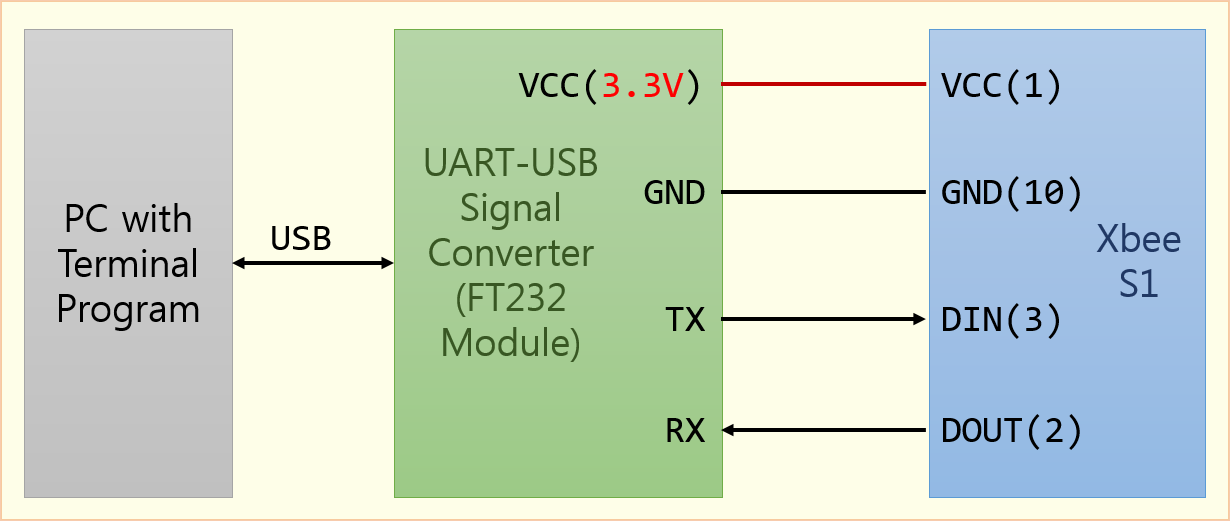
3. Connect an XBee S1 module to a PC via virtual COM port using UART-USB Signal Conversion module (FT-232 module).
4. Set the XBee S1 modules baud rate to 9,600 bps (default value) using one of the following methods.
A. XCTU software (refer to X-CTU user manual)
(1) Run XCTU program.
(2) Click "Add Device" button at the upeer-left corner of the XCTU window.
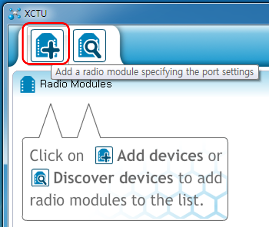
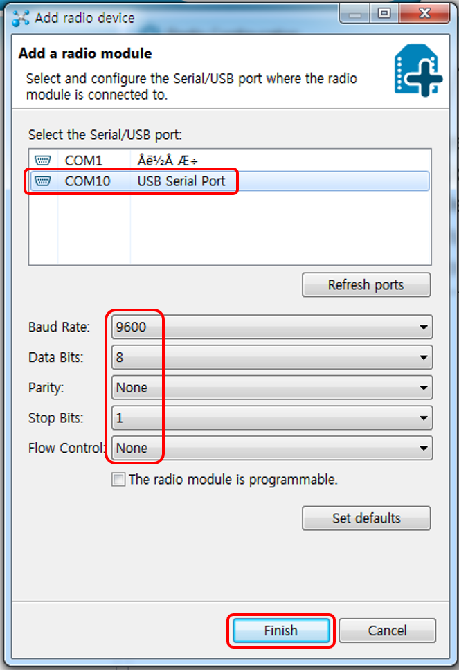
(3) Select the virtual COM port number, Baud Rate, Data Bits, Parity, Stop Bits, Flow Control as indicated in the photo below and click "Finish" button.
(4) XCTU shows a detected XBEE S1 module after scanning.
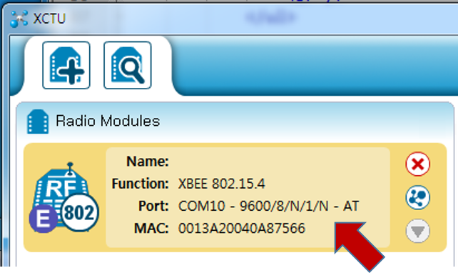
(5) If XCTU cannot detect an XBee S1 module in the step (4), it is considered that the default setting values of the module have been changed.
(A) If the default communication parameters have been changed, repeat step (3) with different communication parameters, for example, different "Baud Rate".
(B) If SM parameter has been changed from its default value (0x00, non-sleeping mode) to different value, for example, 0x01 or 0x02 (both of them are for sleeping mode), connect pin 9 to GND and repeat step (3).
B. AT command via terminal program (refer to AT command section of the XBee S1 datasheet
(1) Run terminal program. In this example, "Tera Term" terminal program is used.
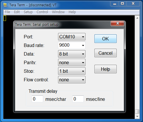
(2) Select "Setup" -> "Serial port..." menu. In the "Tera Term Serial port setup" dialog, select Port (the virtual COM port number), Baud Rate (9600), Data Bits (8), Parity (none), Stop (1 bit), Flow control (none) and click "OK" button.
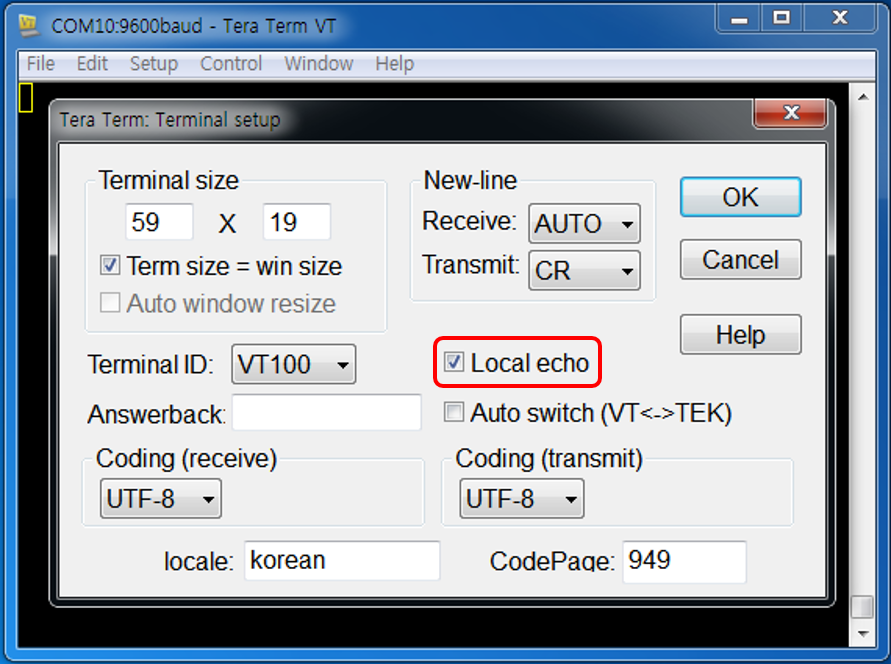
(3) Select "Setup" -> "Terminal" menu. In the "Tera Term Terminal setup" dialog, click "Local echo" and click "OK" button.
(4) In the Tera Term terminal window, type +++ (without 'Enter') and wait. Terminal shows OK message to indicate that the XBEE S1 module is connected. This means that all of the communication are correct. You can change XBee S1 parameters using AT command. Once confirmed, type ATCN and press "Enter" key to disconnect.
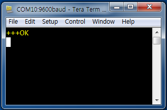
(5) If the XBee S1 cannot be detected by Tera Term terminal program in the step (4), follow the steps A (5).
5. Basic wireless communication test between two XBee S1 modules.
A. Connect the first XBee S1 module to a virtual COM port of a PC through FT232 module and open terminal program.
B. Change the first XBee S1 module's operation mode to AT command mode by typing '+++' command.
C. Confirm that the XBee S1 module responds 'OK'.
D. Escape AT command mode using 'ATCN' command once it responds 'OK'.
E. Connect the second XBee S1 module to a different virtual COM port of the same PC through FT232 module and open one more terminal program. (You can use a different PC.)
F. Repeat the above step B, C and D for the second XBee S1 module.
G. Once both XBee S1 modules are functioning properly, type any character at one terminal and you can see that the same character is displayed at the other terminal program.
Step II: Transmitter Test I (Transmission time interval is controlled by a delay function)
1. In this example, one of the XBee S1 modules will be programmed as a simple transmitter and the other one will be used as a simple receiver without programming. The receiver will display input characters on its terminal screen whatever it receives.
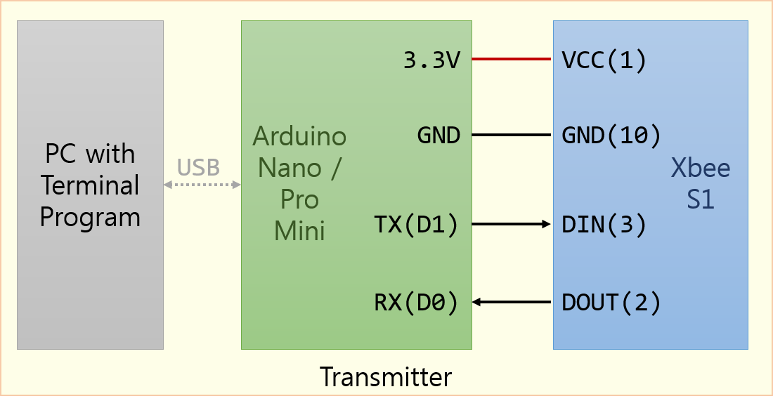
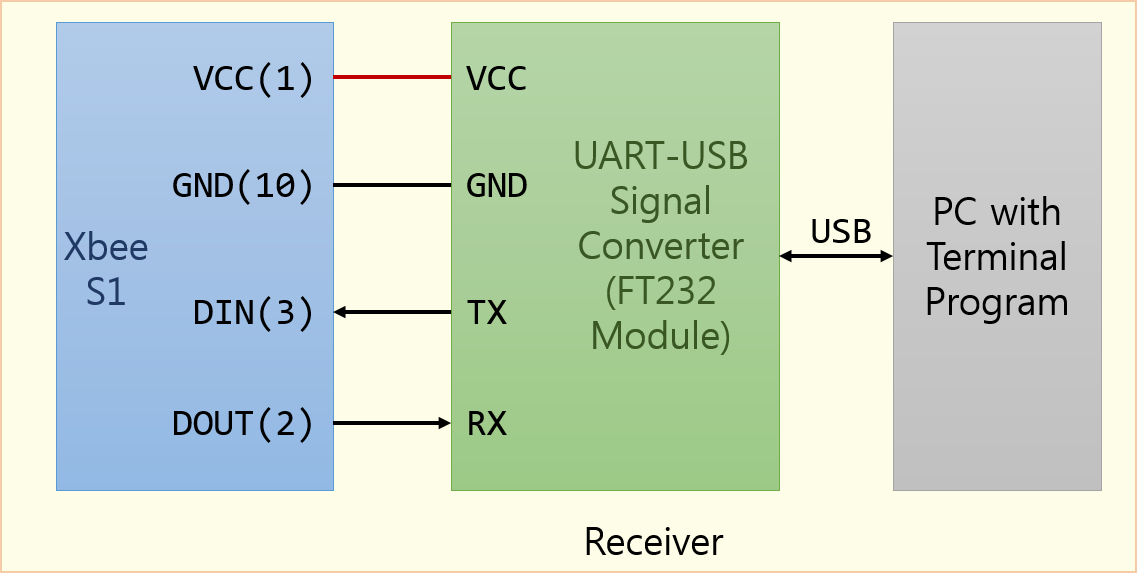
2. Connect the first XBee S1 module to an Arduino Nano or Arduino Pro Mini module as shown in the above figure. (This Arduino module will operates as a transmitter.)
3. Keep the receiver connections as it was used in Step I.
4. Make a test program for the transmitter which transmits a simple test message. Start with CodeVision AVR, and
A. Set the Clock frequency at 2 MHz.
B. Select USART (including TX and RX) and set the baud rate to 9600 bps.
5. Use a delay_ms() function call so that the test program transmits one test message every ten seconds.
6. Write the test program to the ATmega328P of the transmitter (Arduino Nano or Arduino Pro Mini) and run it. The message sent from transmitter must be displayed at the receiver terminal every ten seconds.
Source Code for Step II developed by Hazirah.
/*****************************************************
Project : Bed Alarm
Version : STEP II
Date    : 1/4/2015
Author  : Hazirah

Chip type               : ATmega328P
Program type            : Application
AVR Core Clock frequency: 2.000000 MHz
*****************************************************/

#include <mega328p.h>
#include <stdio.h>
#include <delay.h>

void main(void)
{
    // Crystal Oscillator division factor: 8.
    // fclk will be 16MHz/8 = 2MHz
    CLKPR=0x80;
    CLKPR=0x03;

    // USART initialization
    // Communication Parameters: 8 Data, 1 Stop, No Parity, Baud Rate: 9600 bps
    // USART Receiver: On, Transmitter: On
    UCSR0A=0x00;
    UCSR0B=0x18;
    UCSR0C=0x06;
    UBRR0H=0x00;
    UBRR0L=0x0C;

    // Set XBee S1 to AT Command mode
    delay_ms(1000);
    printf("+++");
    delay_ms(1000);

    // set XBee S1 to TRANSPARENT mode
    printf("ATAP0\r");
    delay_ms(1000);

    // exit AT command mode
    printf("ATCN\r");
    delay_ms(1000);

    while (1)
    {
        printf("Transmitter Test 1\n");
        delay_ms(10000);                //delay 10s
    }
}
Notes on the code for Step II:
(Refer to the command descriptions for the 'AP' and 'CN' commands of the XBee S1 operation manual.)
After reset an Xbee S1 module is operating in TRANSPARENT mode by default. However, if this mode had changed to other than TRANSPARENT mode, for example API mode, the XBee S1 module does not work in a way what we want.
We need to change the XBee S1 mode temporarily in TRANSPARENT mode and the codes between line #32 and line #43 are needed for this purpose.
The Xbee S1 module go back to its previous mode after power off because the current mode change is not written to non-volatile memory but volatile memory.
Step III: Transmitter Test II (Transmission time interval is controlled by timer interrupt)
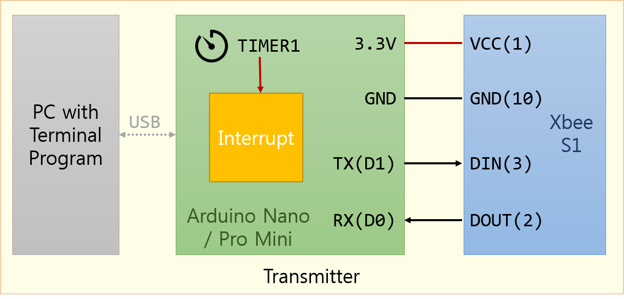

1. Keep the Receiver connections as it was used in Step I and II.
2. Modify the previous transmitter program used in Step II as following.
A. Set up the Timer1 of ATmega328P so that it generates an interrupt every ten seconds.
B. A test message is transmitted whenever Timer1 generates an interrupt.
3. Confirm that the test message is received and displayed at the receiver terminal every ten seconds.
Source Code for Step III developed by Hazirah.
/*****************************************************
Project : Bed Alarm
Version : STEP III
Date    : 1/4/2015
Author  : Hazirah

Chip type               : ATmega328P
Program type            : Application
AVR Core Clock frequency: 2.000000 MHz
*****************************************************/

#include <mega328p.h>
#include <stdio.h>

// Timer1 output compare A interrupt service routine
interrupt [TIM1_COMPA] void timer1_compa_isr(void)
{
    printf("Interrupt1\n");
}

void main(void)
{
    // Crystal Oscillator division factor: 8.
    // fclk will be 16MHz/8 = 2MHz
    CLKPR=0x80;
    CLKPR=0x03;

    // Timer/Counter 1 initialization
    // Clock source: System Clock (2 MHz)
    // Clock value: 2 MHz/1024=1953.125 Hz
    // Mode: CTC top=OCR1A
    // Timer1 Overflow Interrupt: Off
    // Input Capture Interrupt: Off
    // Compare A Match Interrupt: On
    // Compare B Match Interrupt: Off
    TCCR1A=0x00;
    TCCR1B=0x0D;    // System Clock / 1,024(decimal)
    TCNT1H=0x00;
    TCNT1L=0x00;
    ICR1H=0x00;
    ICR1L=0x00;
    OCR1AH=0x4C;    // OCR1AH:OCR1AL=0x4C4B=19,531(decimal)
    OCR1AL=0x4B;
    OCR1BH=0x00;
    OCR1BL=0x00;

    // Timer/Counter 1 Interrupt(s) initialization
    TIMSK1=0x02;

    // USART initialization
    // Communication Parameters: 8 Data, 1 Stop, No Parity, 9600 bps
    // USART Receiver: On
    // USART Transmitter: On
    // USART0 Mode: Asynchronous
    UCSR0A=0x00;
    UCSR0B=0x18;
    UCSR0C=0x06;
    UBRR0H=0x00;
    UBRR0L=0x0C;

    // Global enable interrupts
    #asm("sei")

    while (1)
    {
        // Do nothing.
    }
}
Notes on the code for Step III:
It works perfectly.
Current system clock frequency F_clk is 2 MHz, and it is divided by 1,024 by the Timer1 prescaler.
Thus, the input clock frequency to the Timer1 F_timer1 is 2 MHz/1024=1953.125 Hz.
Since 0x4C4B (19531 in decimal) was written to OCR1A, the frequency of Timer1 interrupt is 1953.125Hz/19531=0.1 Hz.
In other words, Timer1 generates interrupt every 10 seconds.
One tip to become a professional programmer
In general, the interrupt service routine should be short in terms of execution time because other urgent work cannot be done as long as the CPU is executing an interrupt service routine. Thus, it would be better to modify the program so that the Timer1 interrupt is serviced in a short time as following.
We prepare one external (global) variable (timer1_intr_flag in line #15 of the code below) and Timer1 interrupt service routine simply sets this flag variable to one(1) (in line #20 of the code below) to minimize the execution time of the interrupt service routine.
The CPU continuously checks the value of this flag inside the main loop (inside the while loop in this example, from line #71 to line #79) and does proper work if the flag is set to one(1) (line #75 to line #77).
This flag is cleared in the main loop after finishing the work (line #77).
The improved version of the code is shown below and the variable ten_second is simply added for the fun.
/*****************************************************
Project : Bed Alarm
Version : STEP III (improved version)
Date    : 1/4/2015
Author  : Hazirah

Chip type               : ATmega328P
Program type            : Application
AVR Core Clock frequency: 2.000000 MHz
*****************************************************/

#include <mega328p.h>
#include <stdio.h>

unsigned char timer1_intr_flag;

// Timer1 output compare A interrupt service routine
interrupt [TIM1_COMPA] void timer1_compa_isr(void)
{
    timer1_intr_flag = 1;
}

void main(void)
{
    unsigned int  ten_second = 0;

    // Crystal Oscillator division factor: 8.
    // fclk will be 16MHz/8 = 2MHz
    CLKPR=0x80;
    CLKPR=0x03;

    // Timer/Counter 1 initialization
    // Clock source: System Clock (2 MHz)
    // Clock value: 2 MHz/1024=1953.125 Hz
    // Mode: CTC top=OCR1A
    // Timer1 Overflow Interrupt: Off
    // Input Capture Interrupt: Off
    // Compare A Match Interrupt: On
    // Compare B Match Interrupt: Off
    TCCR1A=0x00;
    TCCR1B=0x0D;    // System Clock / 1,024(decimal)
    TCNT1H=0x00;
    TCNT1L=0x00;
    ICR1H=0x00;
    ICR1L=0x00;
    OCR1AH=0x4C;    // OCR1AH:OCR1AL=0x4C4B=19,531(decimal)
    OCR1AL=0x4B;
    OCR1BH=0x00;
    OCR1BL=0x00;

    // Timer/Counter 1 Interrupt(s) initialization
    TIMSK1=0x02;

    // USART initialization
    // Communication Parameters: 8 Data, 1 Stop, No Parity, 9600 bps
    // USART Receiver: On
    // USART Transmitter: On
    // USART0 Mode: Asynchronous
    UCSR0A=0x00;
    UCSR0B=0x18;
    UCSR0C=0x06;
    UBRR0H=0x00;
    UBRR0L=0x0C;

    // Global enable interrupts
    #asm("sei")

    printf("\nHello, Receiver. I am a Bed Alarm Transmitter.\n");
    printf("You'll get my message every ten seconds.\n\n");

    while (1)
    {
        if (timer1_intr_flag == 1)      // check if Timer1 interrupt occurred
        {
            ten_second++;
            printf("%d seconds elapsed.\n", ten_second*10);     // do some work
            timer1_intr_flag = 0;       // indicate that the Timer1 interrupt service is over.
        }
    }
}
Step IV: Transmitter Test III (Adopting ATmega328P idle mode)
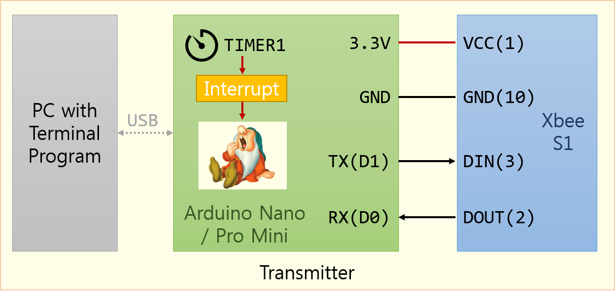

1. Keep the receiver and transmitter connections as they were used in the previous step.
2. Modify the previous transmitter program used in Step III as following.
A. Keep the Timer1 function as it was in Step III, i.e. it generates an interrupt every ten seconds and a test message is transmitted whenever Timer1 generates an interrupt.
B. Prepare system initialization code.
C. Immediately after the system initialization, (inside of while() loop) set the ATmega328P to Idle mode.
D. After ten seconds, Timer1 interrupt wakes up ATmega328P and ATmega328P transmits a test message.
E. Repeats the step C and D.
F. Confirm that the test message is received and displayed at the receiver terminal every ten seconds.
The source code for this test is listed below. It is too simple, isn't it?
A few lines were removed and only two lines were added.
We don't need to set the timer1_intr_flag inside the Timer1 interrupt service routine (line #20). In addition, we do not need to check this flag inside the while loop.
Writing 0x01 to SMCR register followed by execution of #asm("sleep") sets ATmega328P to IDLE mode. Refer to 10.1 Sleep Modes of ATmega328P datasheet.
ATmega328P keeps IDLE mode until Timer1 interrupt occurs. After 10 seconds Timer1 interrupt wakes up ATmega328p. It resumes the next instruction, line #83, after waking up because it has executed line #75 before going to sleep.
You can do some housekeeping work after waking up, for example, read the bed alarm switch status, encode it into a message and transmits it here. In this example, simply increase variable 'ten_second' by one and transmits it at line #83 and #84.
After finishing housekeeping work, it goes to IDLE mode again at line #74 and #75 and repeats this work forever as long as the power supplies.
Source Code for Step IV.
/*****************************************************
Project : Bed Alarm
Version : STEP IV (adopting ATmega328P IDLE mode)
Date    :7/4/2015
Author  : Hazirah

Chip type               : ATmega328P
Program type            : Application
AVR Core Clock frequency: 2.000000 MHz
*****************************************************/

#include <mega328p.h>
#include <stdio.h>
#include <delay.h>


// Timer1 output compare A interrupt service routine
interrupt [TIM1_COMPA] void timer1_compa_isr(void)
{
    // do nothing
}

void main(void)
{
    unsigned int  ten_second = 0;

    // Crystal Oscillator division factor: 8.
    // fclk will be 16MHz/8 = 2MHz
    CLKPR=0x80;
    CLKPR=0x03;

    // Timer/Counter 1 initialization
    // Clock source: System Clock (2 MHz)
    // Clock value: 2 MHz/1024=1953.125 Hz
    // Mode: CTC top=OCR1A
    // Timer1 Overflow Interrupt: Off
    // Input Capture Interrupt: Off
    // Compare A Match Interrupt: On
    // Compare B Match Interrupt: Off
    TCCR1A=0x00;
    TCCR1B=0x0D;    // System Clock / 1,024(decimal)
    TCNT1H=0x00;
    TCNT1L=0x00;
    ICR1H=0x00;
    ICR1L=0x00;
    OCR1AH=0x4C;    // OCR1AH:OCR1AL=0x4C4B=19,531(decimal)
    OCR1AL=0x4B;
    OCR1BH=0x00;
    OCR1BL=0x00;

    // Timer/Counter 1 Interrupt(s) initialization
    TIMSK1=0x02;

    // USART initialization
    // Communication Parameters: 8 Data, 1 Stop, No Parity, 9600 bps
    // USART Receiver: On
    // USART Transmitter: On
    // USART0 Mode: Asynchronous
    UCSR0A=0x00;
    UCSR0B=0x18;
    UCSR0C=0x06;
    UBRR0H=0x00;
    UBRR0L=0x0C;

    printf("\nHello, Receiver. I am a Bed Alarm Transmitter.\n");
    printf("You'll get my message every ten seconds.\n\n");

	// Global enable interrupts
    #asm("sei")

    while (1)
    {
        printf("ATmega328P is going to IDLE mode. %d seconds elapsed\n\r", ten_second*10);
        SMCR = 0x01;    // Set ATmega328P to IDLE mode
        #asm("sleep")   // Now, let ATmega328P fall in sleep

        // ATmega328P keeps IDLE mode until Timer1 interrupt occurs.

        // Now, 10 seconds elapsed and Timer1 interrupt waked up ATmega328p.
        // Do some housekeeping work here.
        // For example, read bed alarm switch status, encode it into a message and transmits it here.
        // In this example, simply increase variable 'ten_second' by one and transmits it.
        ten_second++;
        printf("\n\rATmega328P waked up! %d seconds elapsed\n\r", ten_second*10);
    }
}
Step V: Transmitter Test IV (Adopting XBee Sleep mode)
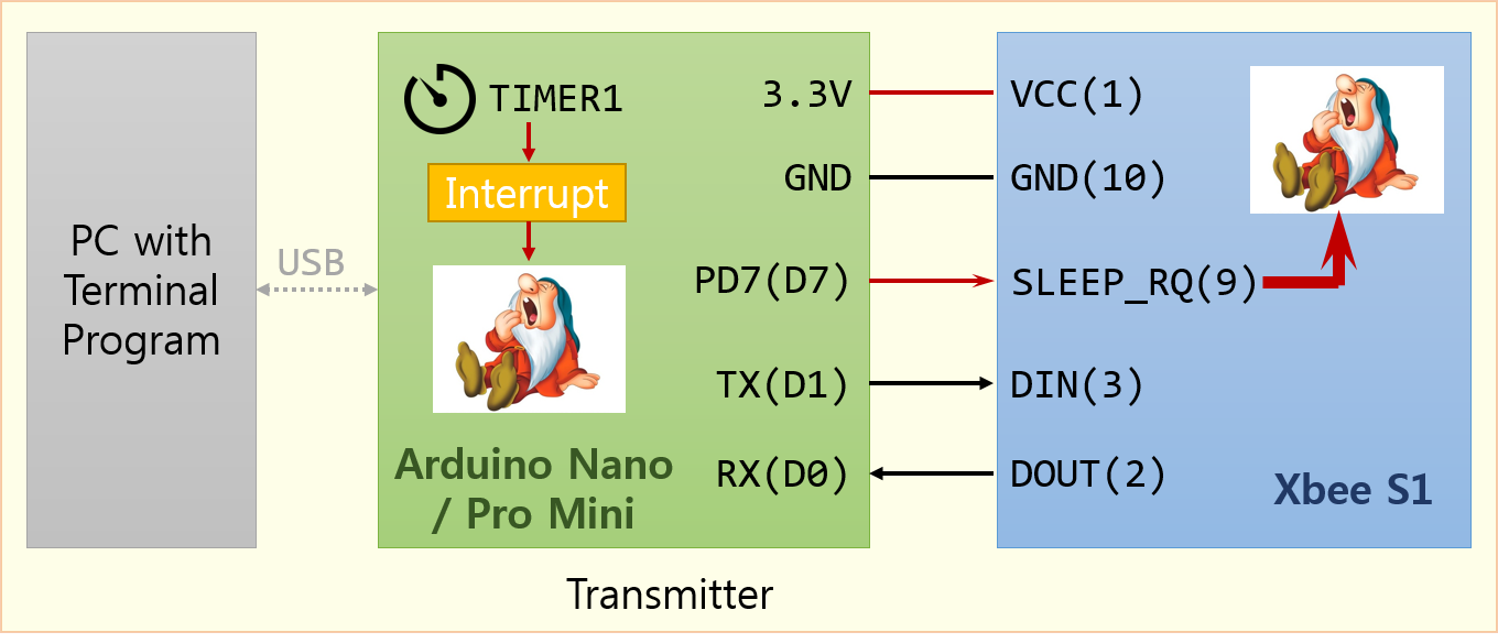

1. Keep the receiver connections as it was used in Step I, II, III and IV.
2. Change SM parameter of XBee S1 from SM=0 to SM=1.
Change the SM parameter from 0 (default, never sleep mode) to 1 (Hibernate) using X-CTU or terminal program as mentioned in Step I.
This SM parameter is used to control the sleeping mode of XBee S1. However, an XBee S1 module never goes to sleep mode by pulling up the SLEEP_RQ(pin 9) as long as SM=0. Refer to the description of sleeping modes and SM parameter in the operation manual.
3. Connect SLEEP_RQ signal (pin 9) of the transmitter’s XBee S1 module to PD7(D7) of the Arduino Nano / Arduino Pro Mini. This signal will be used to control the sleep/wake-up of XBee S1.
4. Modify the previous program used in Step IV.
A. Keep all of the functions as they were in the previous step.
B. Set the transmitter’s XBee S1 module in sleep mode by changing the voltage level of the SLEEP_RQ signal(pin 9) before the ATmega328P goes in idle mode.
C. While the transmitter’s ATmega328P stays in idle mode, the transmitter’s XBee S1 module keeps in sleep mode.
D. The transmitter’s ATmega328P wakes up first when Timer1 generates an interrupt and it wakes up the transmitter’s XBee S1 module by changing the voltage level of the SLEEP_RQ control pin.
E. Transmitter transmits a test message and repeats the step B, C, D and E.
F. Confirm that the test message is received and displayed at the receiver terminal every ten seconds.
Source for Step V is listed below and the added lines are highlighted.
Two lines were added for initialization of PORTD bit 7 (Line #38 and #39) - this pin controls voltage level of the SLEEP_RQ(pin 9).
The XBee S1 goes to SLEEP mode by pulling up the SLEEP_RQ(pin 9) / PD7 to HIGH and this is done by the code in line #84.
After XBee S1 went to SLEEP mode, ATmega328P also goes to SLEEP mode by the codes in line #86 and #87.
This SLEEP mode continues until Timer1 of ATmega328P generates interrupt.
ATmega328P resumes execution from line #96 after waking up since the last line that ATmega328P has executed before going to SLEEP mode was line #87.
The XBee S1 will wake up by pulling down the SLEEP_RQ(pin 9) / PD7 to LOW by line #92. According to operation manual of XBee S1 (pp.31-32), however, XBee S1 needs 10.2 ms for wake-up from Hibernate or 2.6 ms from Dose. The statement in line #93 provides this wake-up time.
This 11 msec can be considered waste of time and battery power. If so, you can modify the source code so that you can do the housekeeping work during that 11 msec delay time (wake-up time) as long as it does not use the XBee S1 under waking-up.
Source Code for Step V (Transmitter Test IV).
/*****************************************************************
Project : Bed Alarm
Version : STEP V (adopting XBee S1 Dose / Hibernate mode)
Date    :7/4/2015
Author  : Hazirah

Chip type               : ATmega328P
Program type            : Application
AVR Core Clock frequency: 2.000000 MHz
==================================================================
Connection between XBee S1 and Atmega328P for SLEEP mode control
------------------------------------------------------------------
Sleep_RQ (pin 9) of XBee S1  --------- PD7 of ATmega328P
******************************************************************/

#include <mega328p.h>
#include <stdio.h>
#include <delay.h>


// Timer1 output compare A interrupt service routine
interrupt [TIM1_COMPA] void timer1_compa_isr(void)
{
    // do nothing
}

void main(void)
{
    unsigned int  ten_second = 0;

    // Crystal Oscillator division factor: 8.
    // fclk will be 16MHz/8 = 2MHz
    CLKPR=0x80;
    CLKPR=0x03;

    // Sleep_RQ (pin 9) of XBee S1 is connected to PD7 of ATmega328P
    // XBee S1 goes to SLEEP mode when PD7 is HIGH
    PORTD = 0x00;   // Set PD7 LOW
    DDRD = 0x80;    // Set PD7 as OUTPUT mode

    // Timer/Counter 1 initialization
    // Clock source: System Clock (2 MHz)
    // Clock value: 2 MHz/1024=1953.125 Hz
    // Mode: CTC top=OCR1A
    // Timer1 Overflow Interrupt: Off
    // Input Capture Interrupt: Off
    // Compare A Match Interrupt: On
    // Compare B Match Interrupt: Off
    TCCR1A=0x00;
    TCCR1B=0x0D;    // System Clock / 1,024(decimal)
    TCNT1H=0x00;
    TCNT1L=0x00;
    ICR1H=0x00;
    ICR1L=0x00;
    OCR1AH=0x4C;    // OCR1AH:OCR1AL=0x4C4B=19,531(decimal)
    OCR1AL=0x4B;
    OCR1BH=0x00;
    OCR1BL=0x00;

    // Timer/Counter 1 Interrupt(s) initialization
    TIMSK1=0x02;

    // USART initialization
    // Communication Parameters: 8 Data, 1 Stop, No Parity, 9600 bps
    // USART Receiver: On
    // USART Transmitter: On
    // USART0 Mode: Asynchronous
    UCSR0A=0x00;
    UCSR0B=0x18;
    UCSR0C=0x06;
    UBRR0H=0x00;
    UBRR0L=0x0C;

    printf("\nHello, Receiver. I am a Bed Alarm Transmitter.\n");
    printf("You'll get my message every ten seconds.\n\n");

    // Global enable interrupts
    #asm("sei")

    while (1)
    {
        printf("\n\rATmega328P and XBee S1 are going to IDLE mode.\n\r", ten_second*10);

        PORTD |= 0x80;  // Let XBee S1 fall in SLEEP mode

        SMCR = 0x01;    // Set ATmega328P to IDLE mode
        #asm("sleep")   // Now, let ATmega328P fall in sleep

        // ATmega328P keeps IDLE mode until Timer1 occurs.

        // Now, 10 seconds elapsed and Timer1 interrupt waked up ATmega328p.
        PORTD &= ~0x80;     // Wake up XBee S1
        delay_ms(11);       // XBee S1 needs wake-up time. (refer to Sleep Mode of XBee S1 User Manual, p.31-32)

		// Do some housekeeping work here.
        // For example, read bed alarm switch status, encode it into a message and transmits it here.
        // In this example, simply increase variable 'ten_second' by one and transmits it.
		// You can do the housekeeping work during the 11 msec delay time (wake-up time) as long as it does not use XBee S1.

        ten_second++;

        printf("\n\rATmega328P and XBee S1 waked up! %d seconds elapsed\n\r", ten_second*10);
    }
}
Step VI: Transmitter Test V (Adopting external interrupts)
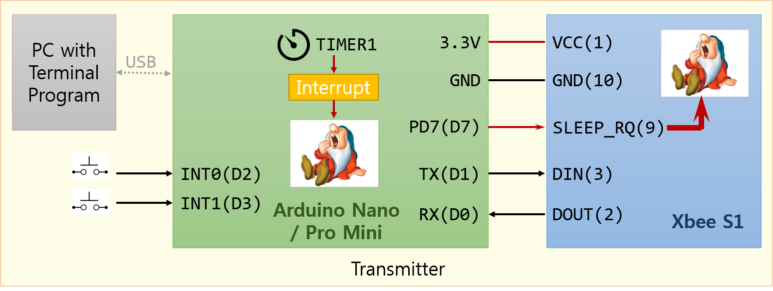

1. Keep the receiver connections as it was used in the previous step.
2. Connect two switch signals to INT0 and INT1 pins of ATmega328P at transmitter.
3. Modify the previous program used in Step V.
A. Keep all of the functions as they were in the previous step.
B. Add initialization code for INT0 and INT1 interrupts. Decide type of interrupt, level trigger or edge trigger, for INT0 and INT1 for this application. You also have to read carefully chapter 10 of the ATmega328P datasheet.
C. Add interrupt service routines for INT0 and INT1 interrupts. After finishing interrupt service, you have to set whole ATmega328P system in sleep mode.
D. Confirm that the test message is received and displayed at the receiver terminal every ten seconds.
Source Code for Step VI which will be developed by Hazirah comes here.
Congratulations!
At the receiver we can decode the received message and use the information for user interface, i.e. to indicates the switches' status and battery level.
You can create unlimited number of applications depending on your imagination. Waiting for your masterpiece...
