How to make a simple application for Nucleo-F411RE in C language
Objective
To program Nucleo-F411RE in C language without using HAL driver
Environment
- MS Windows 7 Professional K (64-bit)
- IAR Embedded Workbench for ARM 7.30.3.8061 (Kick Start version)
- Nucleo-F411RE Board
Getting Started...
1. Start IAR Embedded Workbench for ARM (EWARM) IDE.
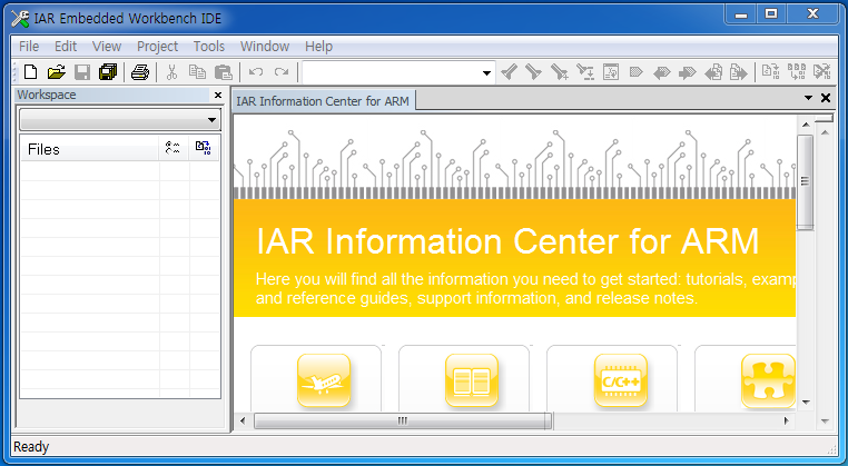
2. Select Project -> Create New Project menu item.
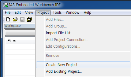
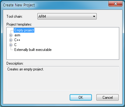
A. In the Create New Project dialog box, select ARM for Tool chain, Empty project in the Project templates pane and click OK button.
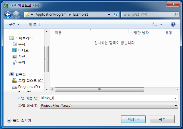
B. Give the project name (Blinky_1) and save the project file in your favorite folder.
EWARM IDE creates settings folder and a batch file, Blinky_1.Debug.cspy.bat, in the settings folder. You can find the project name, Blinky_1, in the Workspace pane.
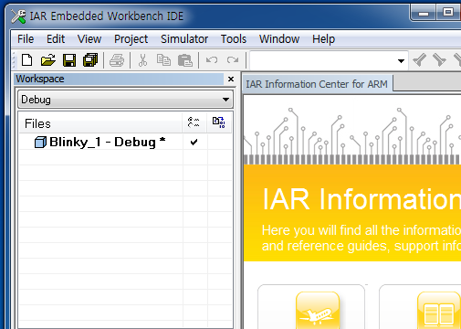
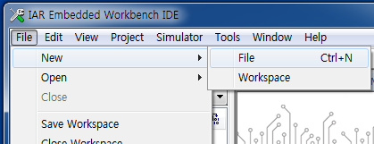
3. Select File -> New -> File menu item to make a main function.
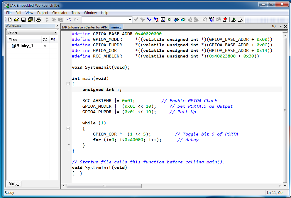
Make a simple application in C language, which toggles the LED connected to bit 5 of PORTA.
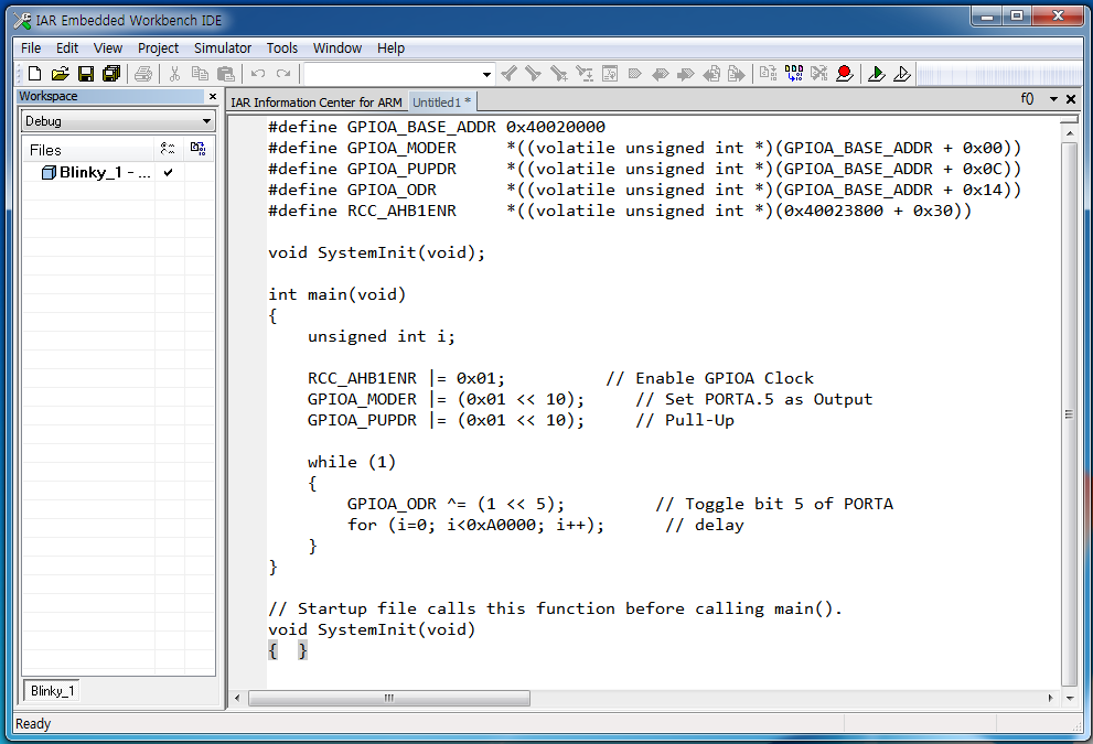
Blinky_1 Program List
#define GPIOA_BASE_ADDR		0x40020000
#define GPIOA_MODER			*((volatile unsigned int *)(GPIOA_BASE_ADDR + 0x00))
#define GPIOA_PUPDR     	*((volatile unsigned int *)(GPIOA_BASE_ADDR + 0x0C))
#define GPIOA_ODR       	*((volatile unsigned int *)(GPIOA_BASE_ADDR + 0x14))
#define RCC_AHB1ENR     	*((volatile unsigned int *)(0x40023800 + 0x30))

void SystemInit(void);

int main(void)
{
    unsigned int i;

    RCC_AHB1ENR |= 0x01;          // Enable GPIOA Clock
    GPIOA_MODER |= (0x01 << 10);     // Set PORTA.5 as Output
    GPIOA_PUPDR |= (0x01 << 10);     // Pull-Up

    while (1)
    {
        GPIOA_ODR ^= (1 << 5);         // Toggle bit 5 of PORTA
        for (i=0; i<0xA0000; i++);      // delay
    }
}

// Startup file calls this function before calling main().
void SystemInit(void)
{  }
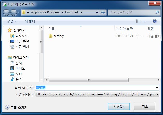
4. Save the file as main.c in the project folder.
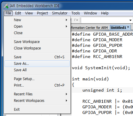
Now, you can see that the name of the edit pane changed to main.c and some parts of the code also changed colors.
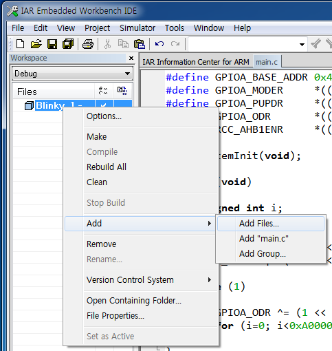
5. Select Project -> Add Files… menu item to add main.c file to the project. You can do this by right-clicking over the project name (Blinky_1) in the left-side Workspace pane.
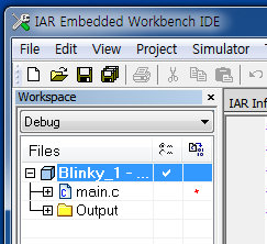
Now, you can find that the main.c is a part of the project by checking the Workspace pane.
6. We need to add startup file (startup_stm32f411xe.s) to our project for complete application. This startup file is provided and can be found in the following folder or other example folders.
\STM32Cube_FW_F4_V1.4.0\Projects\STM32F411RE-Nucleo\Templates\EWARM\startup_stm32f411xe.s
Copy this startup file to the project folder and add it to the project in the same way as in the step 5.

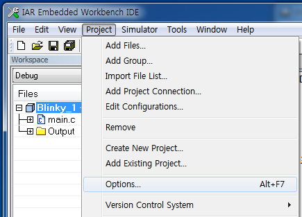
7. Select Project -> Options… menu item to customize building environment for our project.
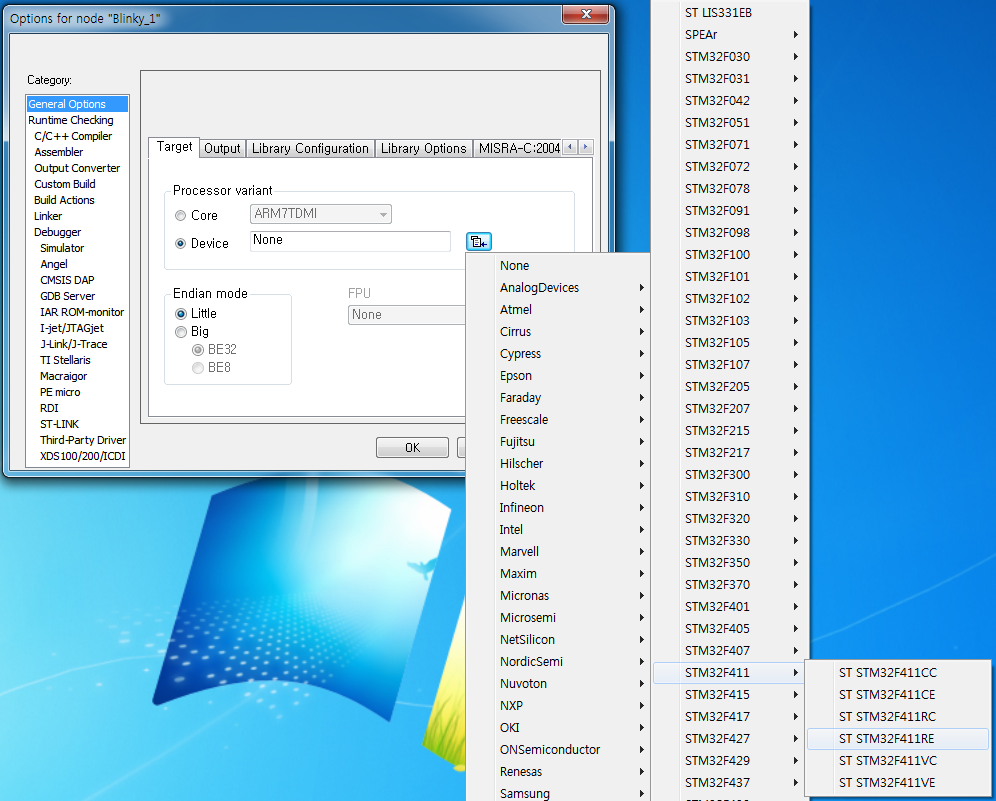
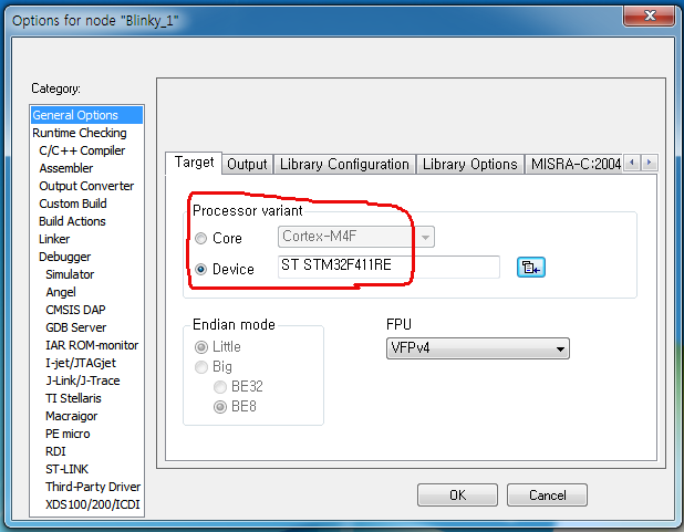
- Click the Device radio button and click the small button located at the right of Device edit control and you can see the list of chip makers.
- Select ST -> STM32F411 -> STM32F411RE which is used in Nucleo-F411RE board.
- Now you can see the device name (ST STM32F411RE) in the Device edit control.
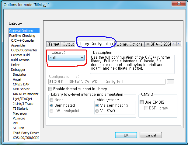
- Select Full in the Library list box.
- Enter 84 for CPU clock.
- Enter 2000 for SWO clock.
A. Select General Options in the Category pane at the left-side of the dialog box.
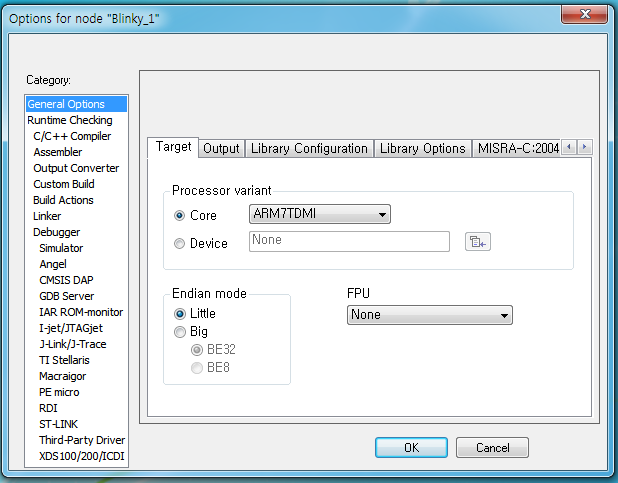
I. Select Target tab at the right-side pane.
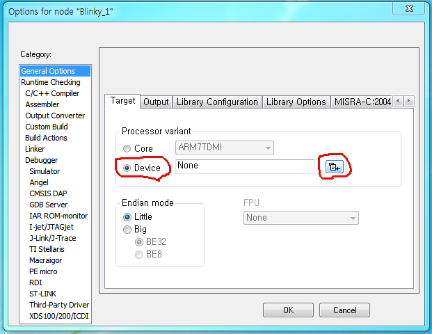
II. Select Library Configuration tab.
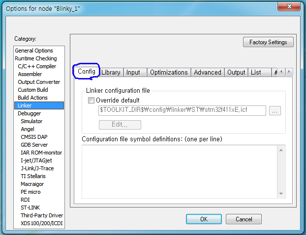
B. Select Linker in the Category pane and select Config tab.
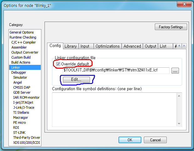
In the Linker configuration file pane, check Override default check box and click Edit… button.
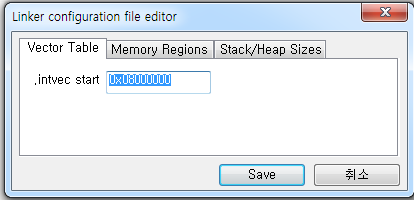
I. Select Vector Table tab.
In the .intvec start edit control, enter 0x08000000 which is the start address of the internal Flash memory and interrupt vector table will be located from this address.
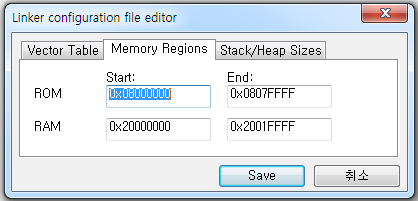
II. Select Memory Regions tab.
Set the addresses as following and click Save button.
|
Start: |
End: |
ROM |
0x08000000 |
0x0807FFFF |
RAM |
0x20000000 |
0x2001FFFF |
C. Select Debugger in the Category pane.
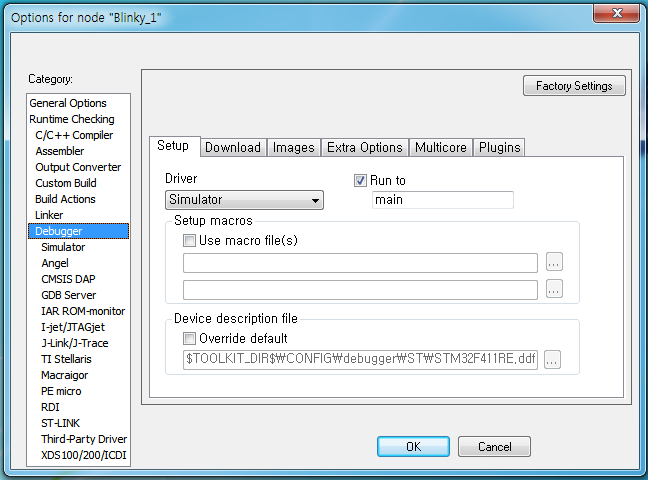
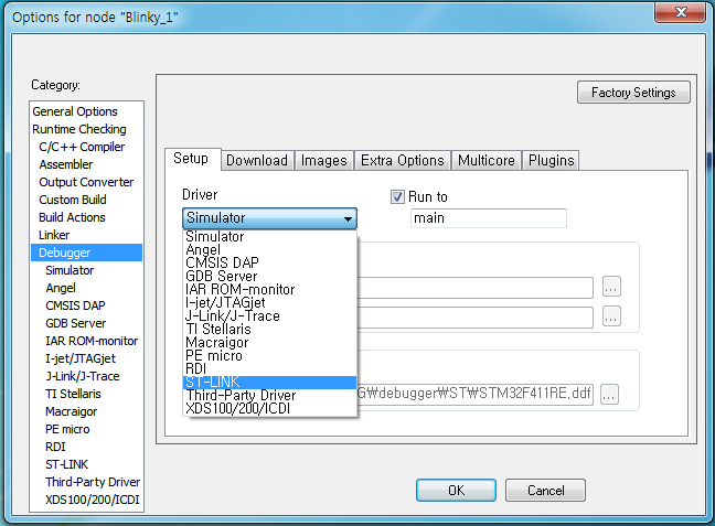
I. Select Setup tab.
In the Driver combo box, select ST-LINK.
II. Select Download tab.
Check Use flash loader(s) radio button.
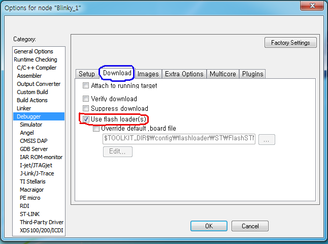
D. Select ST-LINK in the Category pane and it has ST-LINK tab only.
In the Reset pane, select Connect during reset.
In the Interface pane, select SWD.
In the Clock setup pane,
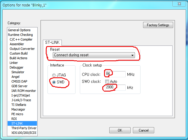
Click OK button to close Option for node “Blinky_1” dialog box.
8. Select File -> Save Workspace As menu item.
Give the workspace file name and save this file in the project folder.
9. Select Project -> Rebuild All menu item.
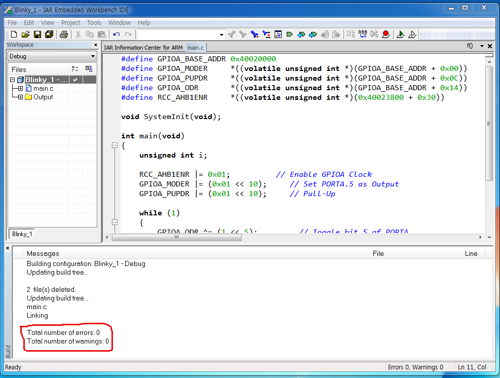
10. Connect the Nucleo-F411RE board to the PC using USB mini cable. This tutorial assumes that the driver files for Nucleo-F411RE board is already installed on the PC.
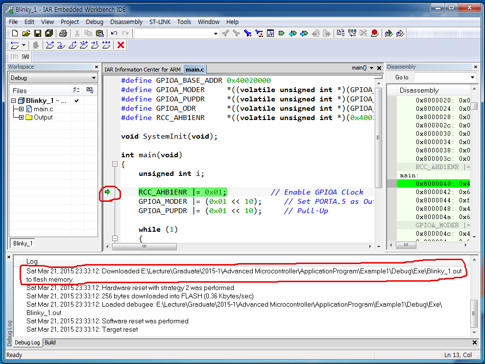
11. Select Project -> Download and Debug menu item.
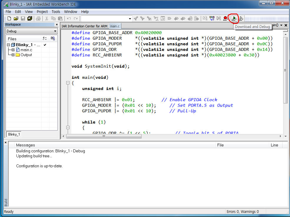
Once downloading completed, you can see the message in the Log pane.
12. Select Debug -> Go menu item.
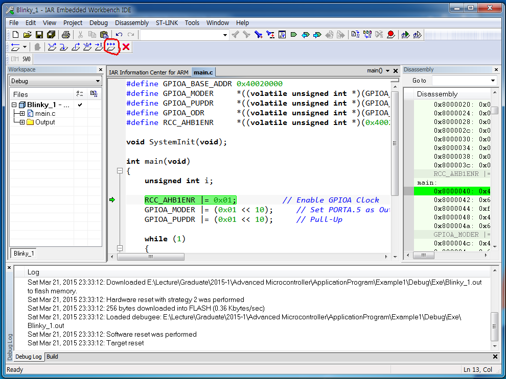
13. Now you can see that the green LED on Nucleo-F411RE board is blinking.

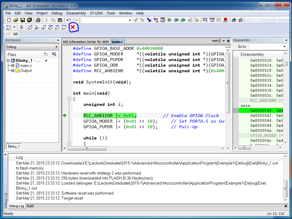
14. Click Stop Debugging button if you want to stop debugging.
Congratulations!
We could make a very simple STM32F411RE application without HAL driver provided by STMicroelectronics.
